I recently purchased from Axminster a Sieg SC2 Lathe, and SX2 Milling Machine. To my dismay there was no way to tell how many RPM’s the spindles were turning. When I looked at the price of the add on LCD display, I was shocked to learn that they sell for £150 each!
Thinking that a simple chip and LCD display in a tacky white plastic box should cost more like £15 I set off on a quest to build my own.
I began by posting a thread on this forum inquiring about the “pinout” of the RPM port on these machines and was lucky enough to get a response that directed me to “macpod.net” where a guy named Jeffery Nelson had done the grunt work of analyzing the data on the seven pin “RPM” port located on a number of Sieg machines including mine.
BTW he sells an Arduino kit to make your own for £50. Alas me being the cheapskate I am decided to go it on my own,
So I started by hitting up Amazon and purchasing an Arduino R3 clone, an LCD display, a couple of enclousures for them, a few Arduino jumpers, and a seven pin plug to match the port on my machines.
My next issue was learning how to program in the Arduino language, which was suprisingly easy as I spent the last 20 years of my career working in the “C++” language which is very similar.
I began by taking a bit of code that Jeffery had written and modified it to write to the I2C type LCD I had chosen, which used two wires for data as compared to the many that the older LCD’s use. It was an interesting journey thru the world of port addresses and interrupts. Having that sorted I uploaded the code to my Arduino R3 clone, and to my amazment it looked as though it may work. I had added some debugging display statements in the code that output to the LCD at each step and to my amazment it ran!
Here is the Pinout from Jeffery’s web site:
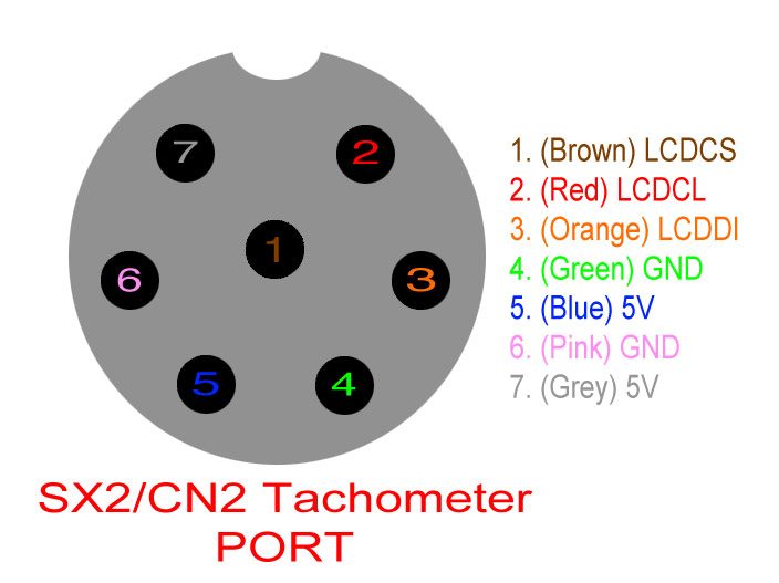
This is the “pinout” of the RPM port on the Seig machines. The drawing is as if you were looking into the port. As you can see there are three data lines, pins 1,2, and 3, and two sets of 5V DC power on pins 4 thru 7. Which Arduino pins to jumper from the Seig RPM port to your Arduino board are defined in the documentation included in my code.
I scoped out the power on pins 4 & 5 and determined it is very clean regulated power at 4.96 Vdc on my lathe and 4.98 Vdc on my mill, perfect to power an arduino board, which solved the issue of needing an external power source to run the board and LCD.
So I hit up good old Amazon and searched for a GX16 type 7 female plug. To my dismay it was the only part of the project I could not find there. Fortunately good ole E-Bay came thru for me, I was able to purchase two of them for a mere £3.
While on Amazon I purchased the remainder of the hardware needed for the project including an Arduino UNO R3 clone, Some arduino jumpers, a bit of heat shrink tubing, an LCD display, and enclosures for the board and display. the total investment for everything was just shy of £30. I am sure you can do even better if you shop around.
First I tackled soldering the five Arduino jumpers to the seven pin connector, which turned out to be tedious. I am sure some choice expletives echoed around my shop while using my antique underpowered soldering iron.
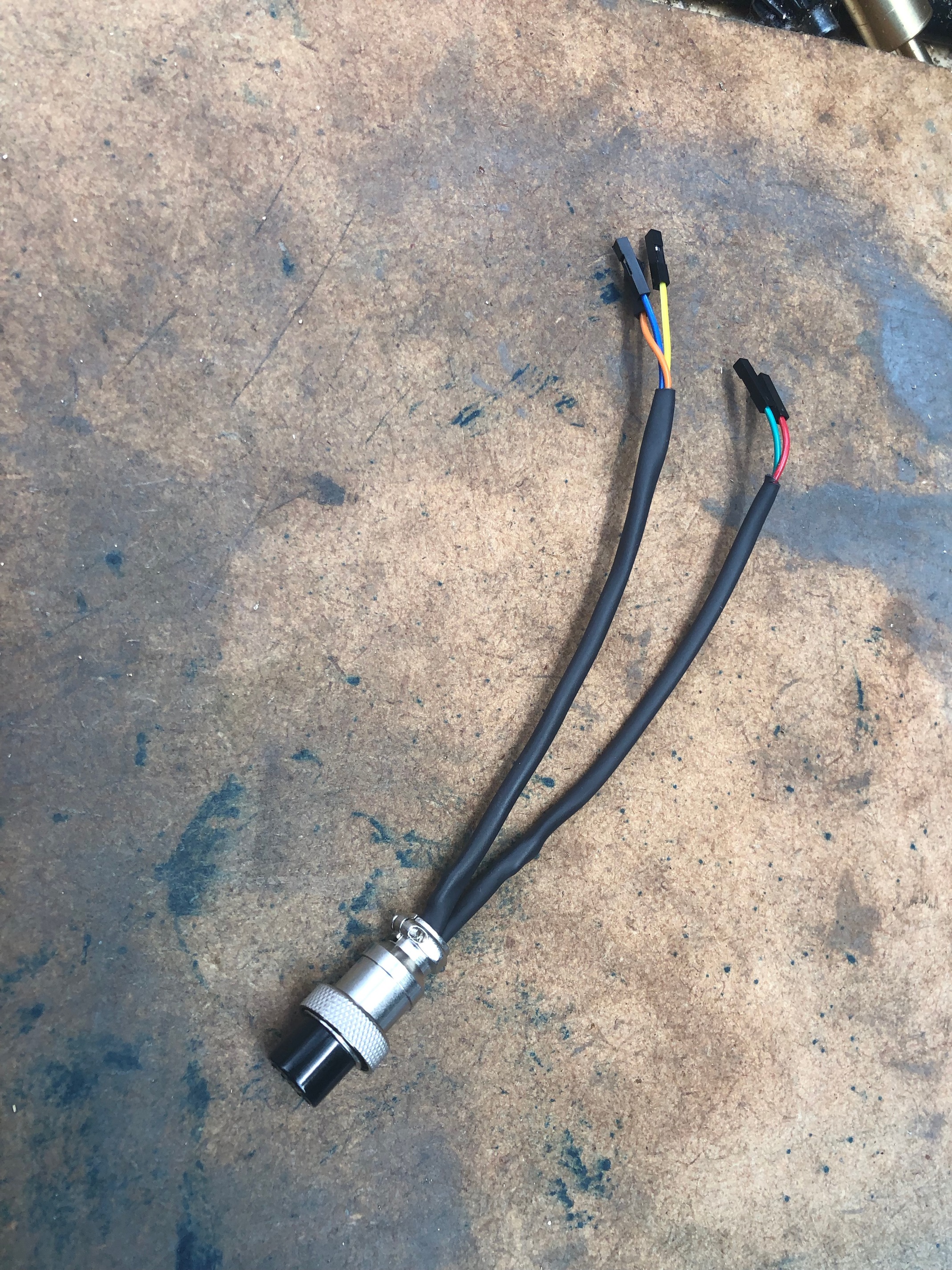
Before assembling the plug I placed a dab of hot glue in the center of the soldered wires and also placed a strip of electrical tape around the outside to insulate the wires from one another and the metal casing on the plug. I finally used a little heat shrinkable tubing to make it pretty.
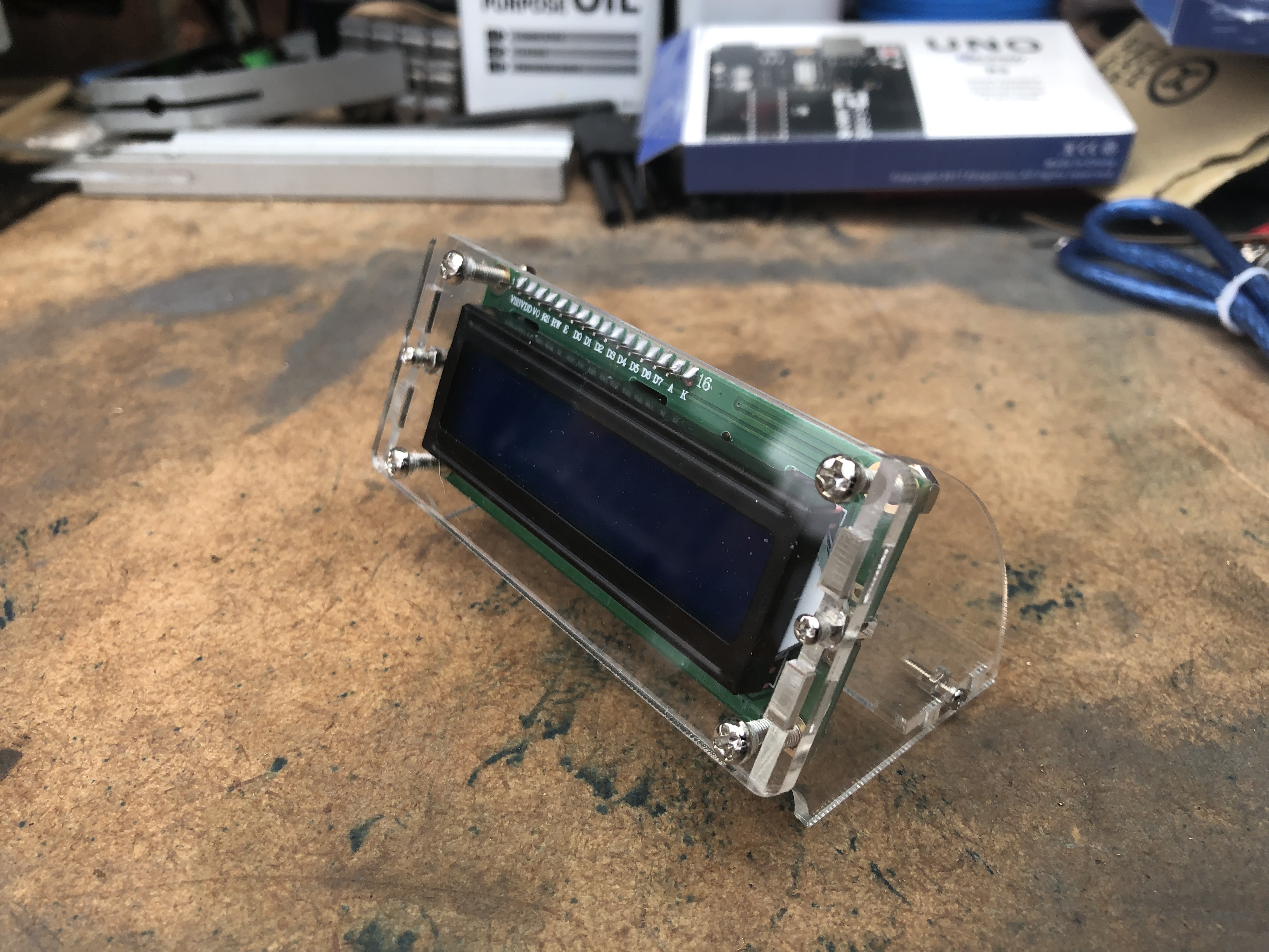
The next step was to assemble the LCD enclosure, which to be honest I do not like as the back is open to the elemens, which in my shop can include flying metal chips. It will be replaced when I re-engineer this prototype and build a single enclosure for the whole project.
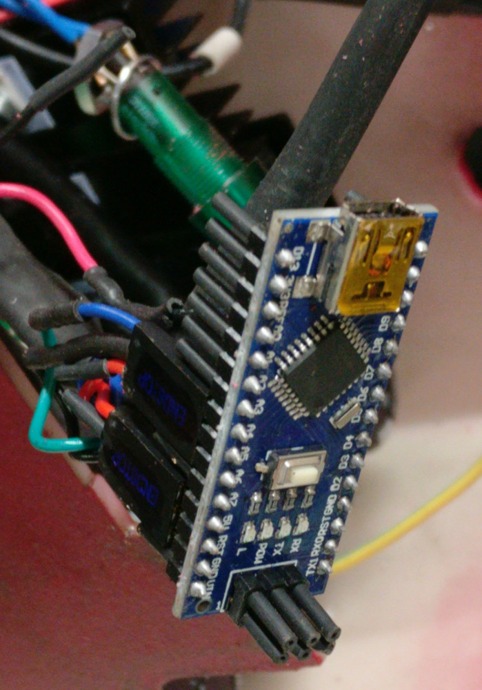
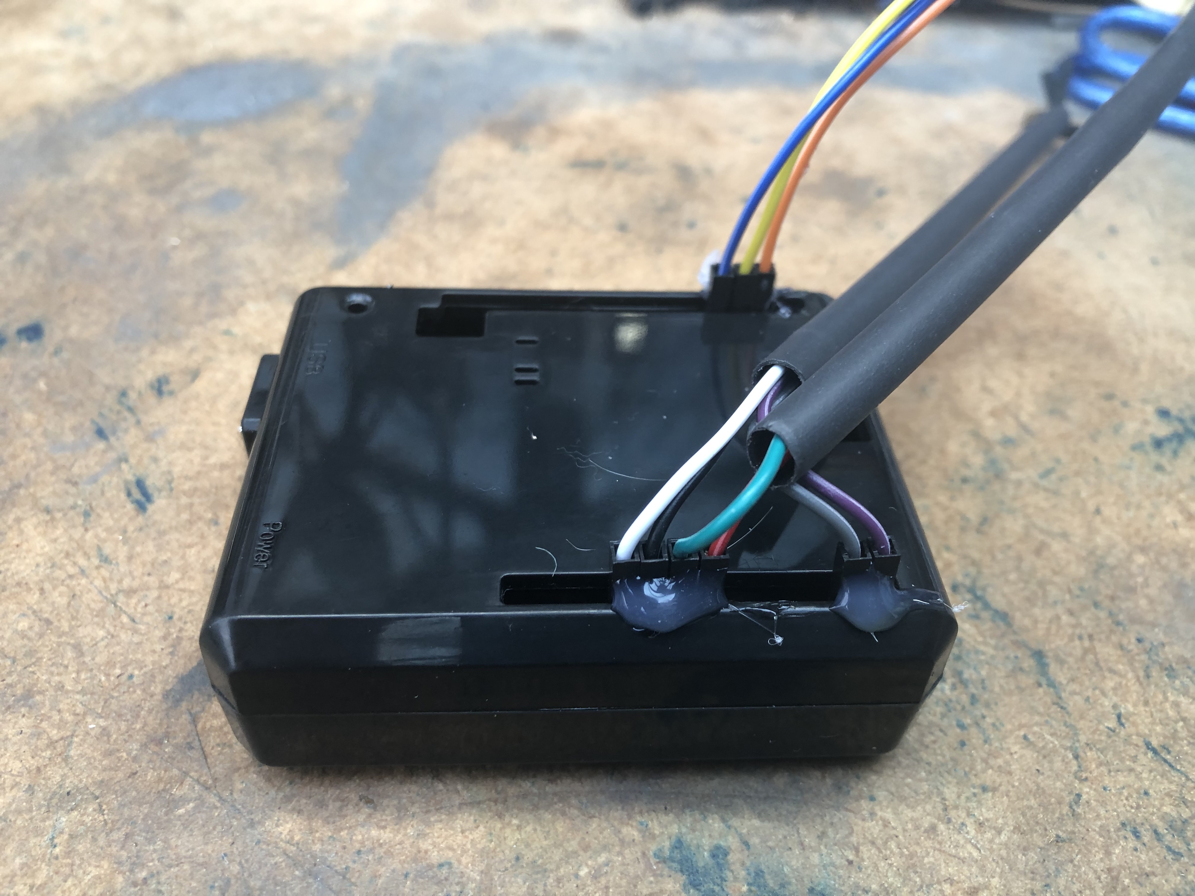
Following this step I placed the R3 clone into its enclosure, attached all the jumpers to the proper pins (which are defined in the code). I put a dab of hot glue on the enclosure where the jumpers were attached just to keep them in place, but still be removable when I disassemble this prototype and build the final enclosure.
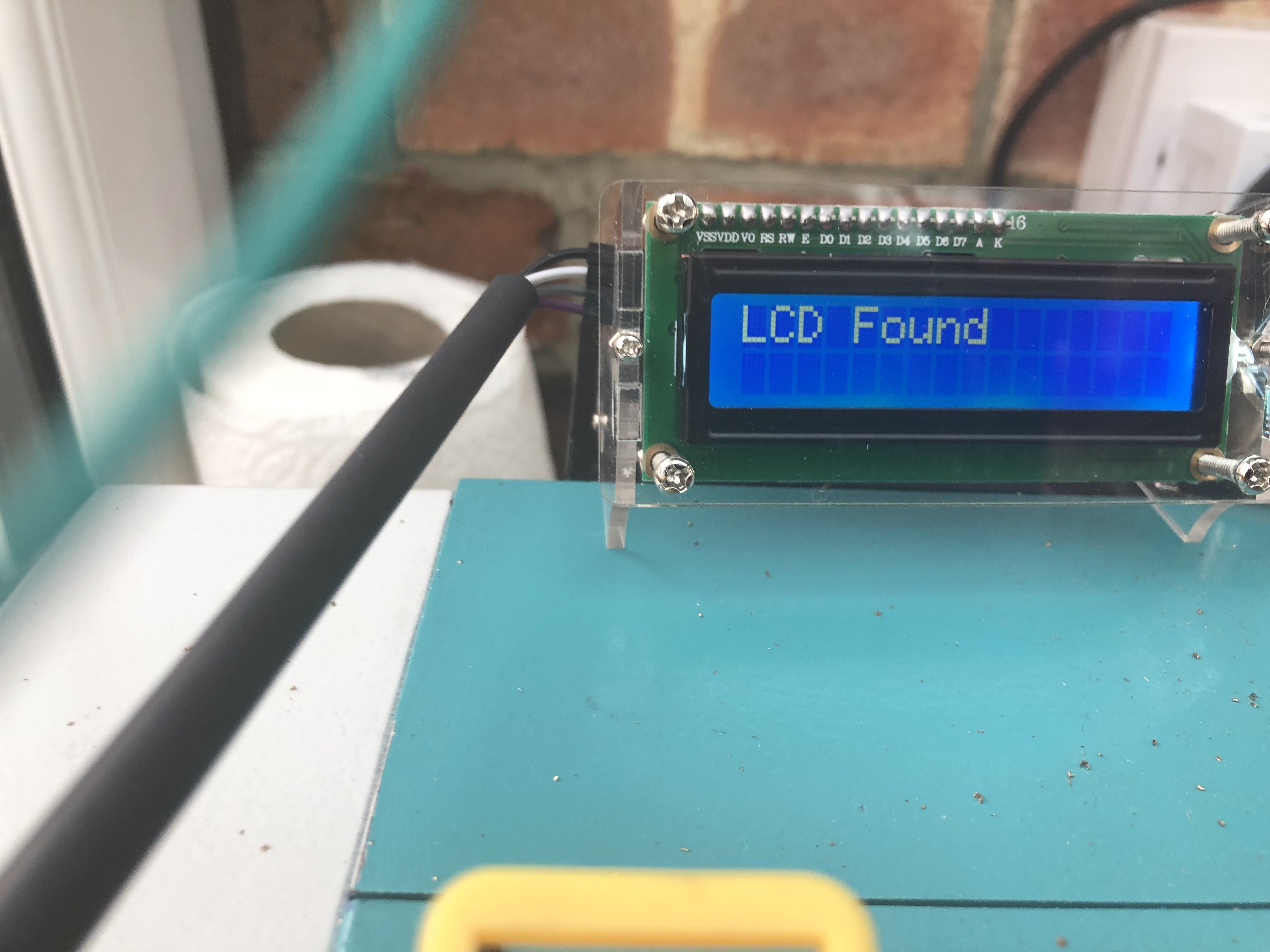
I was now ready to test my code for the first time, a scary moment for any progrmmer. For the first test I chose to use my lathe. I inserted my seven pin plug into the port which is labeled “RPM” and to my amazment the boards LED lit, the display came to life, and displayed my first step message “LCD Found”:
Things were looking good. After another second or so the program header message which is displayed when all the pins are defined and the program is ready to begin looping scanning the port was dislayed:

I just had to see my name in lights!
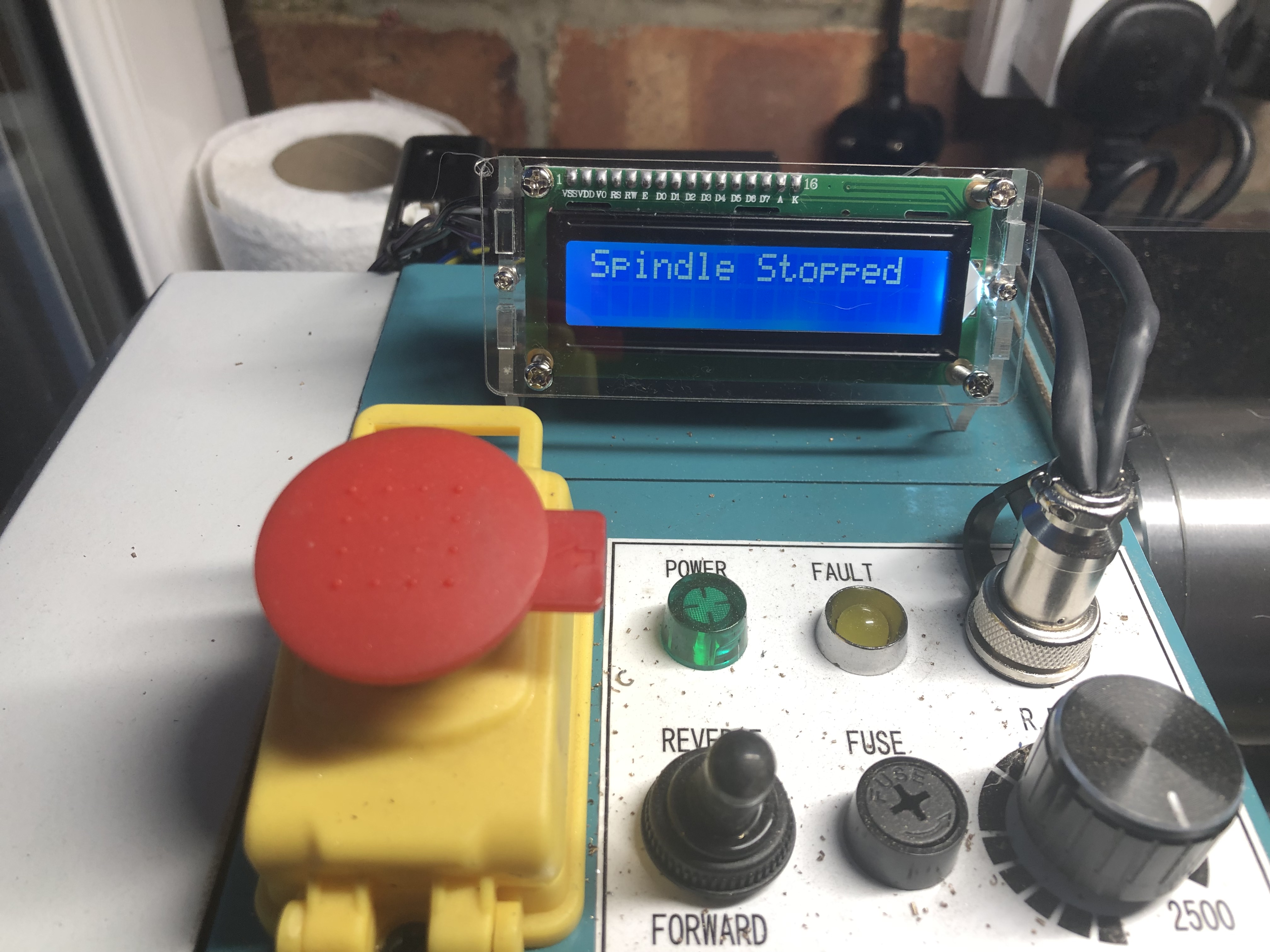
Now the program entered its looping and began reading the four packet groups theat are sent by the Seig controller board. the first message i saw was the “Spindle Stopped” message.
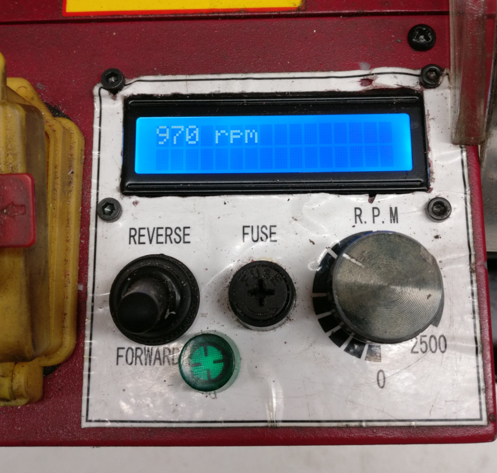
I was really getting excited, the program was behaving as it should, but could it actually read the spindle speed when the packets began to fly? I gingerly twisted the speed control knob a little and to my great pleasure recieved the following:
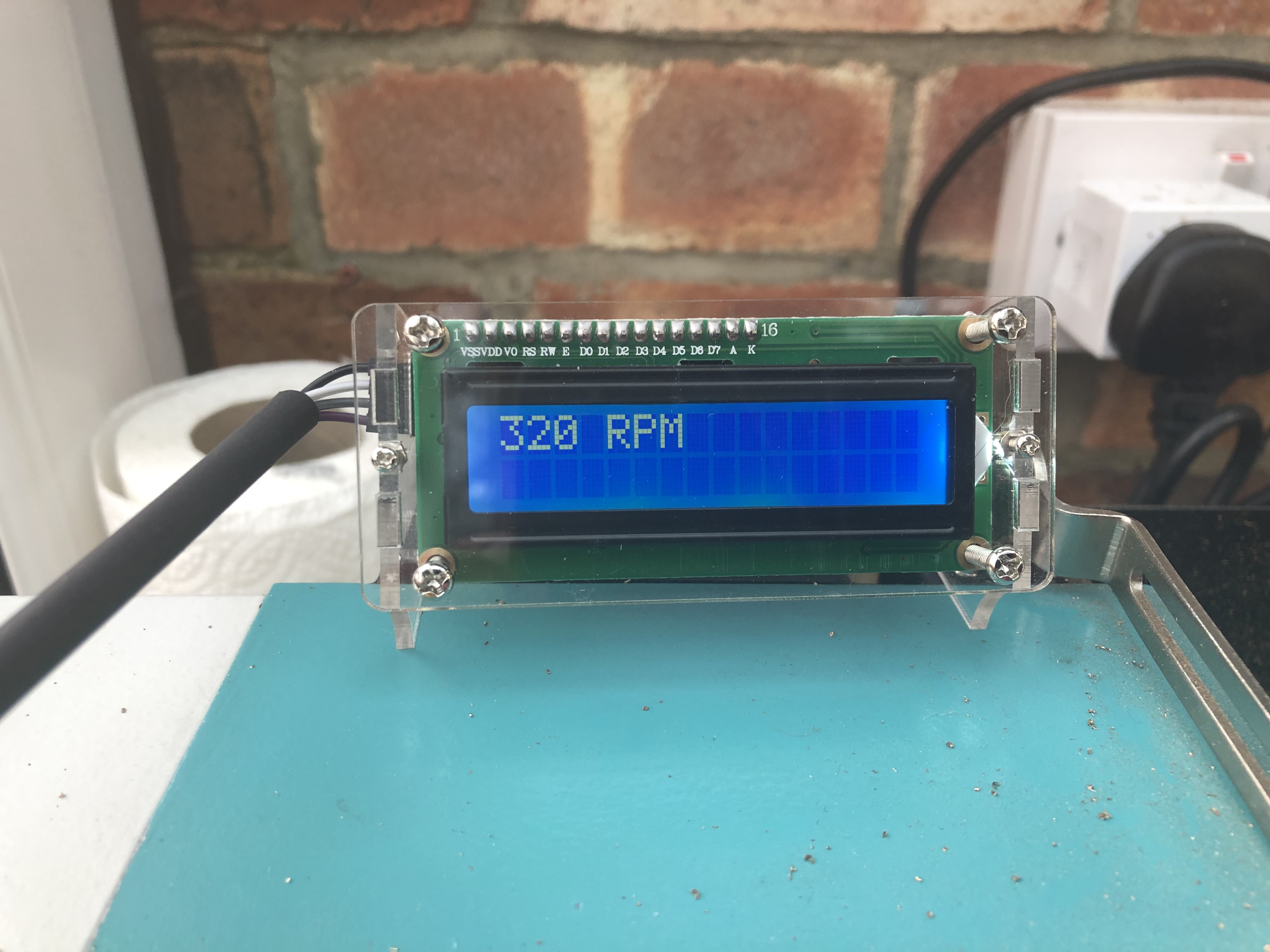
I was in business! the darn thing worked like a charm. Just to be certain I Checked the spindle speed with the strobe application that i mentioned in an earlier post and clocked it at 322 RPM’s not too shabby.
The Sieg controller board transmits the thousands, hundreds and tens column out the RPM port and always leaves the fourth “ones” column at zero. By playing with the strobe I had determined that The controller board rounds the RPMs up the tens column when the ones column speed gets to a six, so from one to 5 rpm you would see a zero displayed, from six to fifteen you would see 10 dispayed and etc… so accuracy of the Sieg data is never more than 5 RPM’s in error. Way more than accurate enough for the model engineer.
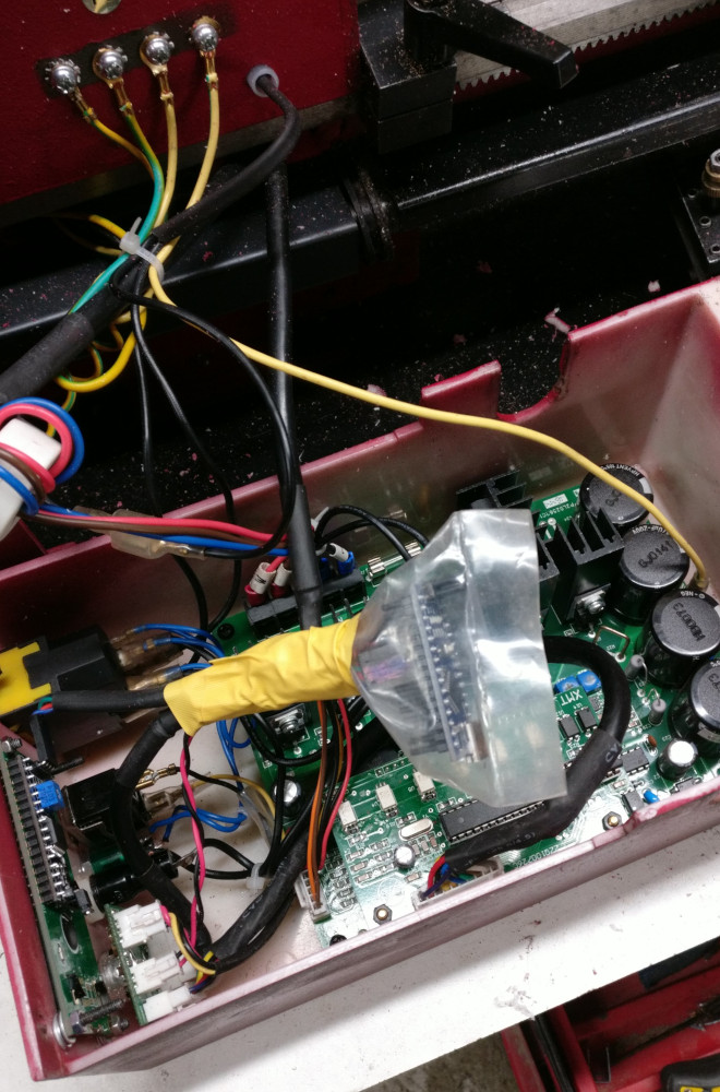
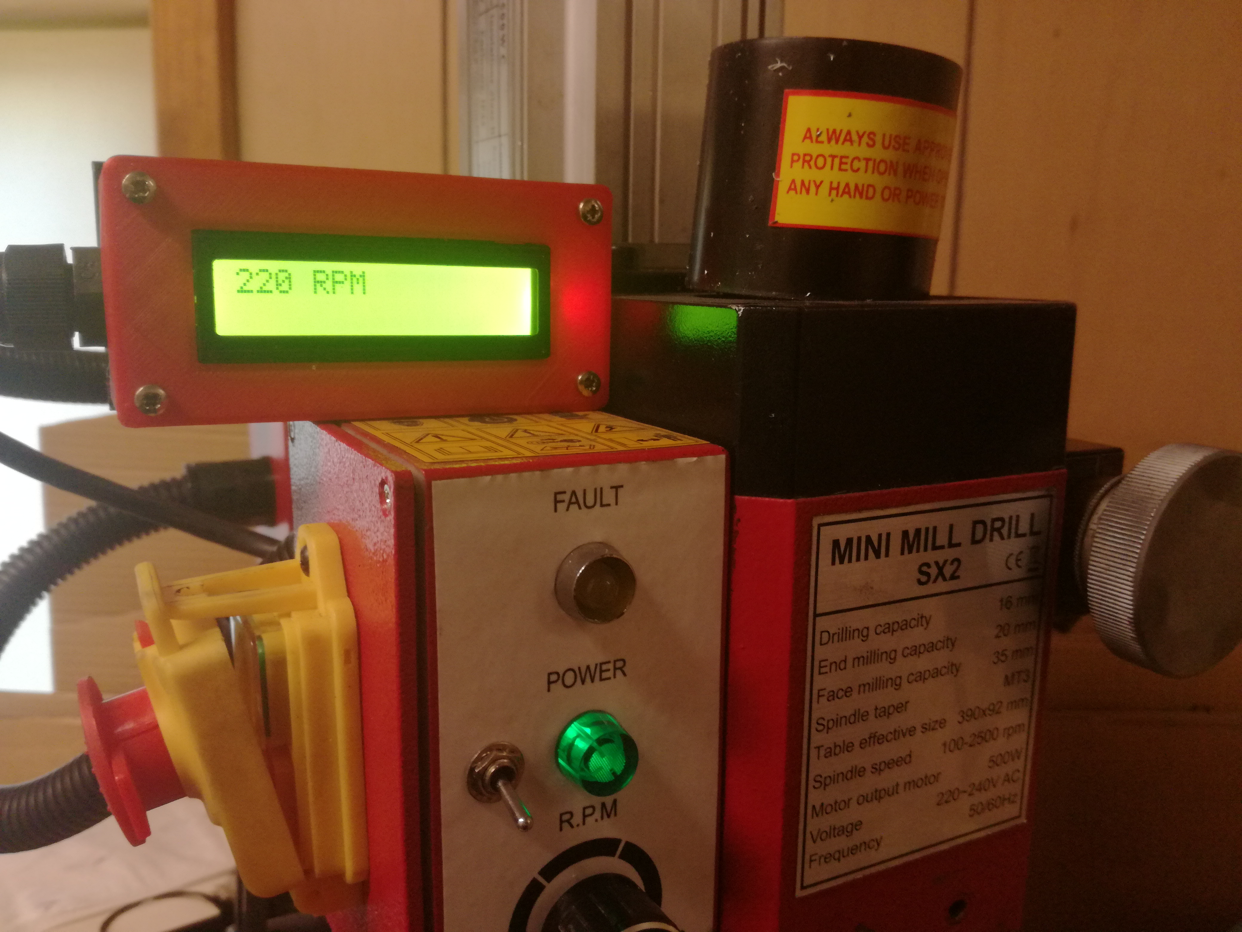
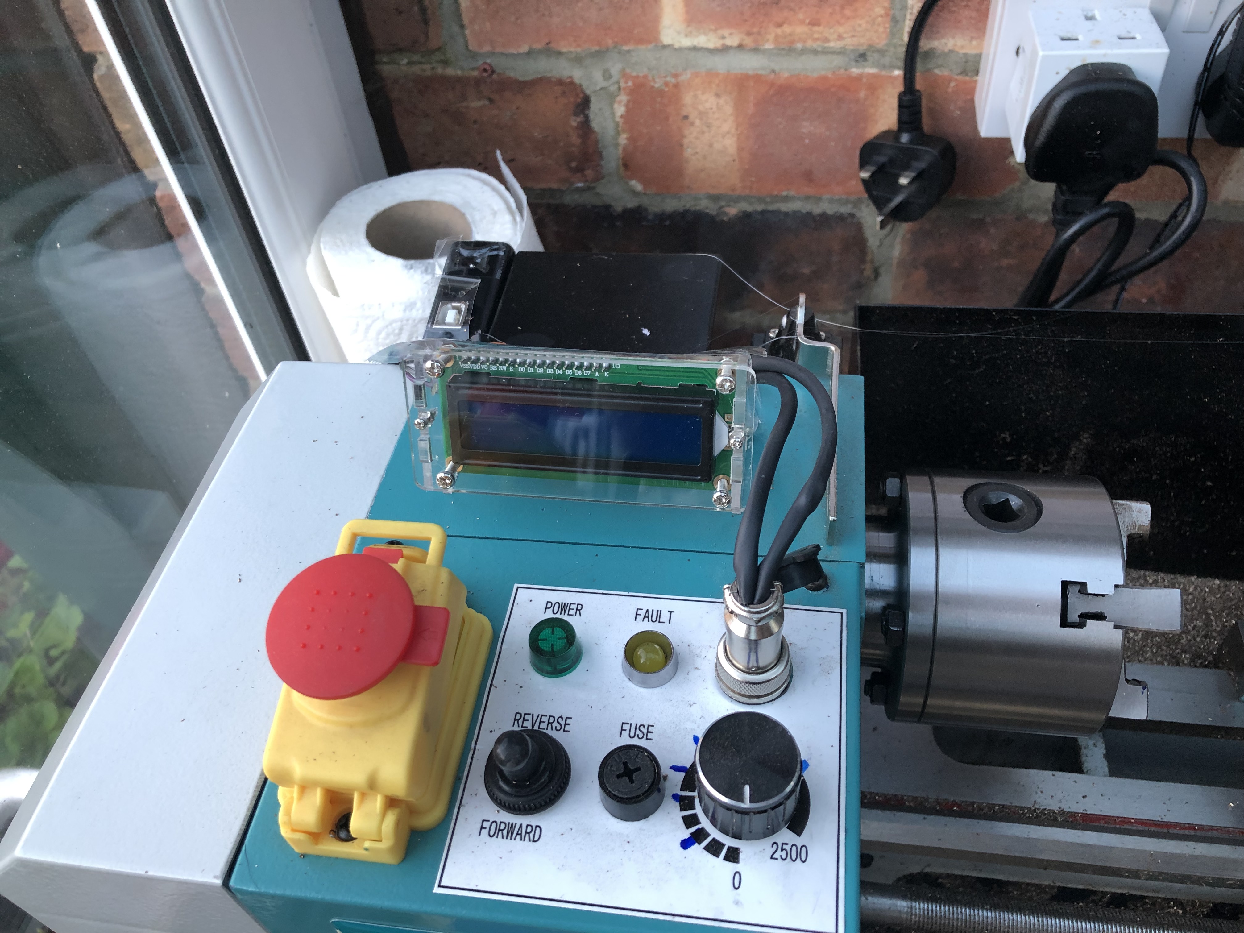
Here is an image of the final product. Using a couple dabs of hot glue I attached the Arduino board on the back side of the lathe’s motor enclosure (visible on back left) and also to the LCD on top where I can easily see it. Notice the port on the Arduino enclosure is facing upwards, so I can easily attach my printer cable to it when and if I apply updates to the program.
Note: I covered the upward facing ports on the Arduino enclosure with a piece of clear cellophane tape, to keep chips and other debris out, also I did the same with the opening on back of the LCD Display.
Conclusion:
This is one way you can beat the high price of the ready made RPM display available from Axminster and other supliers, and have some fun learning to use the Arduino system.
This project goal was to build myself a prototype to verify that I had the coding to run the two wire I2c type LCD and that the code I located on the net was still viable. With this done I will now build a permamant home for my little Arduino project. I will post the final product when i have built its permamant enclosure.
Thank you to Jeffery Nelson for making all the information needed to buld this project on his web site: www.macpod.net available under his “Hacking the SX2 mini mill” heading.
here is the latest non inclusive list of machines that this code works with:
Sieg Industries - SX2 Mini Mill Drill
Sieg Industries - SX2L Mini Mill Drill
Sieg Industries - SX2P Mini Mill Drill
Sieg Industries - SX2LF Mini Mill Drill
Sieg Industries - SC2 Mini Lathe
Little Machine Shop - 4190 HiTorque Mini Mill, Deluxe
Little Machine Shop - 3990 HiTorque Mini Mill, Solid Column with Air Spring
Little Machine Shop - 3990 HiTorque Mini Mill, Solid Column
Little Machine Shop - 3960 HiTorque Mini Mill, Solid Column
Little Machine Shop - 3900 HiTorque Mini Mill, Tilting Column
Little Machine Shop - 4100 HiTorque 7x12 Mini Lathe, Deluxe
Little Machine Shop - 4200 HiTorque 7x12 Mini Lathe
Little Machine Shop - 5100 HiTorque 7x16 Mini Lathe
Craftex - CX-Series CX612 - 3/4 HP Mini Mill with Brushless Motor
Finally, I attempted to list the code here in this forum but it was too long to post here.
Thanks for reading, I look forward to your coments,
Jenny
If you would like a copy of the code please e-mail me at:
jen_edwards@rocketmail.com
Good luck! - Jenny